Solids Control Equipment
- Mud Shale Shaker
- Degasser
- Mud Cleaner
- Centrifuge
- Mud Agitator
- Mud Gun
- Jet Mud Mixer
- Centrifugal Pump
- Shear Pump
- Spray Pump
- Vacuum Pump
- Mud Gas Separator
- Ignition
- Drilling Cuttings Dryer
- Filter Press
- Conveyor
Mud Treatment System
- Drilling Fluid Solids Control System
- Water-based Mud Treatment System
- Oil based Mud Treatment System
- Trenchless Mud Treatment System
- Mud Mixing System
- Drilling Fluid Cooling System
- Truck mounted Mud Circulation System
- Barite Recovery System
Tank and Steel Structure
- Rig Mat
- Elevated Diesel Tank
- Nested Water Tank
- Fracturing Fluid Tank
- Drilling Pipe Basket
- Drill Cuttings Box
- Mud Storage Tank
Drilling Tools and Spare Parts
Phone: 86-29-88680837
Mail: sales@hlsolidscontrol.com
Add: Room 804, Building 1, Western Cloud Valley Phase II, Fengxi New Town, Xixian New District, Shaanxi Province
Mud Transfer Pump
Product Overview:
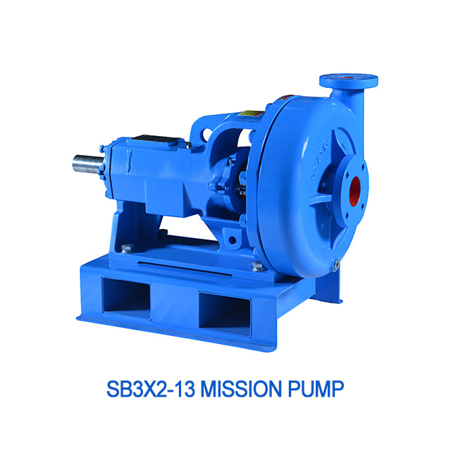
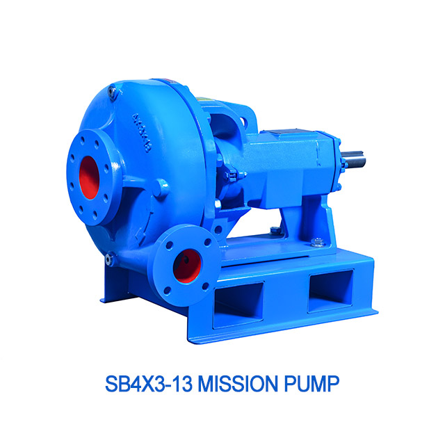
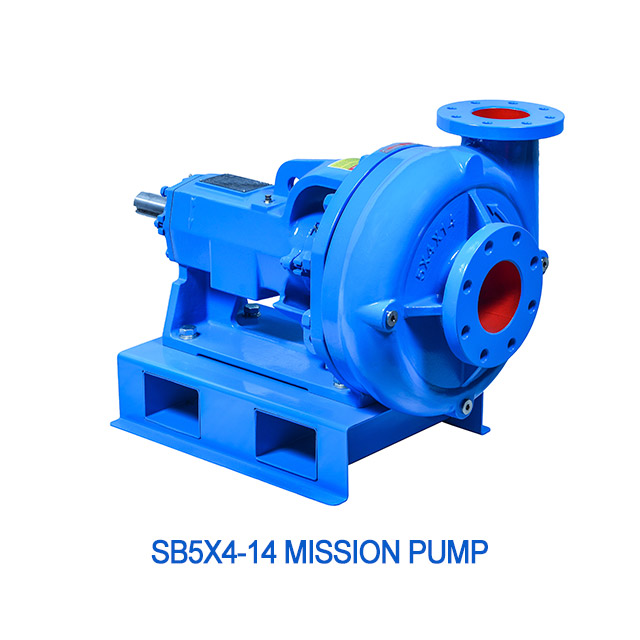
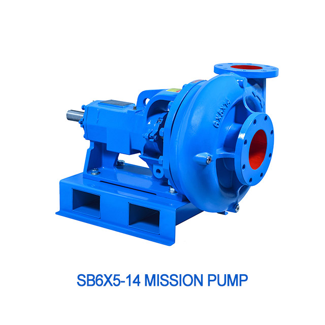
Mud Transfer Pump
1).1320GPM Extra-large flow
2).115ft High-lift
3).6 years Service life
4).Machinery and packing double seal structure
5).Wear resistant cast iron pump shell
6).Metric and imperial two connection methods
7).Low maintenance costs
Mud Transfer Pump Details
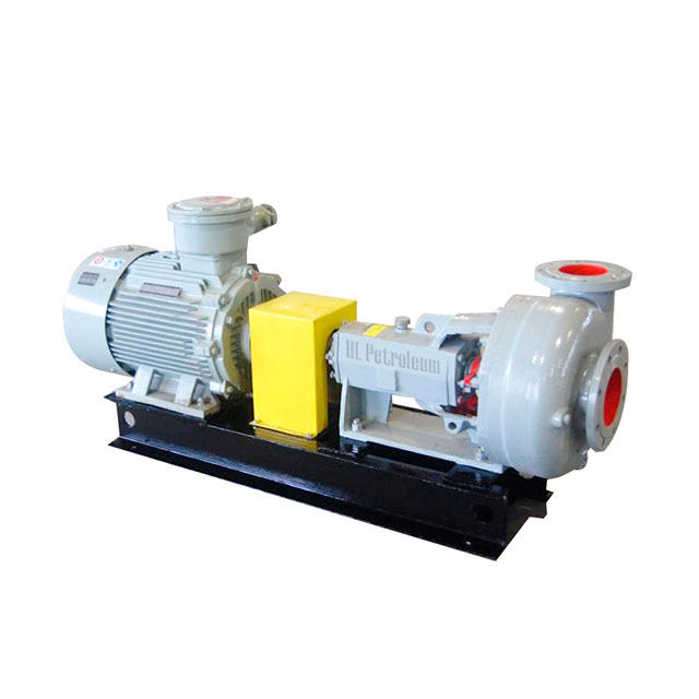
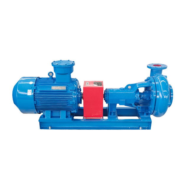
Xi'an HL mud transfer pump is also known as centrifugal sand pump, slurry pump, replenishment pump, perfusion pump, which provides power for desander, desilter and jet mixing device in mud solid control equipment. The ideal supporting equipment can also be used as a mud pump auxiliary filling pump and wellhead supply pump. Mud circulation pump is a kind of centrifugal pump, which can be used to transport larger sand, slag and other suspensions. The impeller is open. The pump seal is a mechanical seal, which is durable. Generally used in oilfield drilling and mining, trenchless mud treatment, shield engineering and other industries industry.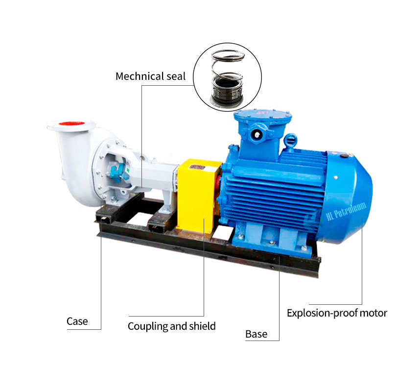
Mud Transfer Pump Parameters
|
Model |
Capacity (m3/h) |
Head (m) |
Efficiency (%) |
NPSH (m) |
Power (kW) |
|
| Shaft power | Motor power | |||||
|
SB8×6-14 |
320 |
40 |
65 |
4.0 |
53.63 |
75 |
|
SB8×6-13 |
290 |
33 |
64 |
4.5 |
40.7 |
55 |
|
SB8×6-12 |
270 |
28 |
64 |
4.5 |
32 |
45 |
|
SB8×6-14I |
200 |
40 |
62 |
3.2 |
35.1 |
55 |
|
SB8×6-13I |
180 |
34 |
60 |
3.0 |
27.8 |
45 |
|
SB8×6-12I |
160 |
30 |
60 |
3.0 |
22 |
30 |
|
SB6×5-14 |
200 |
40 |
62 |
3.2 |
35.1 |
55 |
|
SB6×5-13 |
180 |
34 |
60 |
3.0 |
27.8 |
45 |
|
SB6×5-12 |
160 |
30 |
60 |
3.0 |
22 |
37 |
|
SB6×5-11 |
200 |
21 |
62 |
2.5 |
18.5 |
30 |
|
SB6×5-9 |
160 |
12 |
58 |
3.0 |
9.02 |
15 |
|
SB5×4-14 |
120 |
45 |
56 |
4.6 |
23.3 |
37 |
|
SB5×4-13 |
90 |
40 |
56 |
4.5 |
17.5 |
30 |
|
SB5×4-12 |
90 |
30 |
56 |
4.5 |
13.1 |
22 |
|
SB5×4-11 |
90 |
24 |
56 |
4.5 |
10.5 |
18.5 |
|
SB5×4-10 |
85 |
20 |
56 |
4.2 |
8.4 |
15 |
|
SB5×4-9 |
80 |
19.5 |
54 |
4.5 |
7.9 |
15 |
|
SB4×3-13 |
50 |
40 |
48 |
4.5 |
11.3 |
18.5 |
|
SB4×3-12 |
45 |
30 |
47 |
4 |
7.8 |
15 |
|
SB4×3-11 |
45 |
24 |
46 |
4 |
6.4 |
11 |
|
SB3×2-13 |
25 |
35 |
40 |
3 |
5.9 |
11 |
|
SB3×2-12 |
23 |
29 |
39 |
3 |
5.1 |
7.5 |
|
SB3×2-11 |
20 |
23 |
39 |
3 |
3.2 |
5.5 |

Mud Transfer Pump Using Site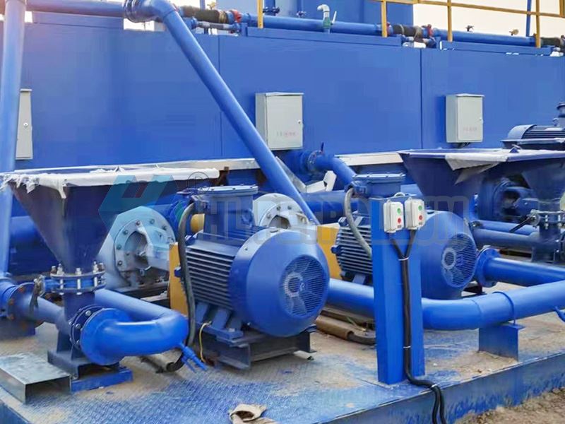
Mud Transfer Pump Structure
The most basic parts of a mud circulations pump are the impeller and the pump casing. The impeller is the heart part of the mud circulation pump. The impellers of ordinary mud circulation pumps are divided into three types: open, semi-open and closed.
The pump casing is the outer shell of the pump body, which surrounds the rotating impeller and is provided with a liquid inlet and a tangential outlet perpendicular to the impeller. The pump forms a snail shell-shaped passage with a gradually expanding cross-sectional area around the impeller, so it often becomes a volute. The pump forms a snail shell-shaped passage with a gradually expanding cross-sectional area around the impeller, so it often becomes a volute. The direction of rotation of the impeller in the shell is to gradually expand along the volute-shaped channel. The closer to the outlet, the greater the amount of liquid received in the shell, so the cross-sectional area of the channel must gradually increase. More importantly, the liquid thrown from around the impeller at high speed gradually reduces its speed in the channel, so that a large part of the kinetic energy is converted into static pressure energy, which not only increases the outlet pressure of the fluid, but also reduces the flow rate of the liquid due to excessive flow. The energy loss caused by the pump body. So the pump casing is the outer casing of the pump, which itself is an energy conversion device.
Mud Transfer Pump Working Principle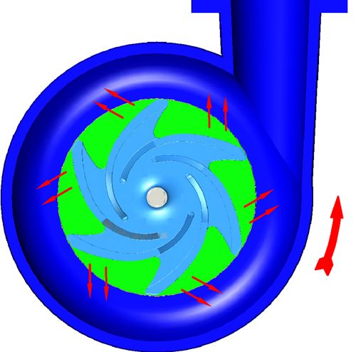
The fluid medium rotates with the impeller, and is thrown from the center of the impeller to the periphery under the action of centrifugal force of inertia, and obtains energy, which increases the static pressure and flow velocity of the fluid medium flowing to the periphery of the impeller. The fluid medium leaves the impeller and enters the pump casing. As the flow passage in the pump casing gradually expands, the fluid speed slows down, and part of the kinetic energy is converted into static pressure energy. Therefore, the fluid medium with higher pressure energy enters the discharge pipeline from the discharge port of the centrifugal sand pump and is transported to the designated pipeline system.

