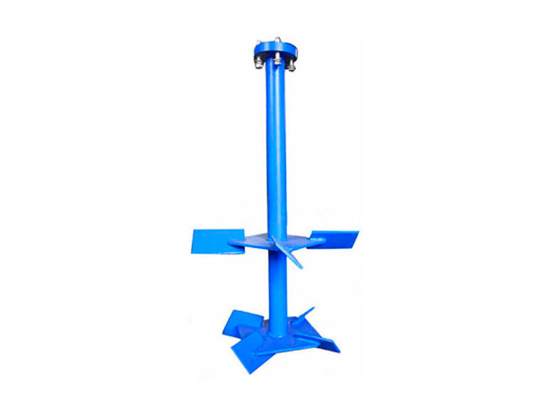
An impeller (also called a turbine) converts mechanical energy into motion of a fluid, such as the impeller of a centrifugal pump. Much research has been done on the design and installation of impellers, and it has been found that each impeller transfers energy to the fluid in two ways:
(1) Pumping capacity
(2) Shear capacity
Impeller design can improve only one of these two capacities, not both. The amount of fluid flowing through an impeller is its pumping capacity, or delivery capacity; most manufacturers have performed extensive testing to determine the flow characteristics and capacity of a particular impeller model and size, but shear rate is rarely predicted. Shear rate is considered to be a velocity gradient with distance. Shear rate can be measured at a point just a few meters from the tip of the impeller and the maximum and average values can be calculated, while shear stress is the product of shear rate and fluid viscosity. For laminar Newtonian fluids, shear stress and shear rate are almost identical.
However, most drilling fluids are non-Newtonian, so the predictions of experimental and theoretical models differ somewhat from the actual situation. The shear rate required for mixing depends on many variables, including impeller design, blade tip speed, distance from the tank wall, baffles, and especially concentration, particle size distribution, drilling fluid density, plasticity, viscosity, static shear, yield value, etc. Laboratory models suggest that proper mixing of drilling fluid components is achieved by eddy flow in the turbulent zone, which is related to the boundaries of the fluid in the tank. Therefore, most manufacturers have a known motion curve for the impeller that is suitable for specific conditions.