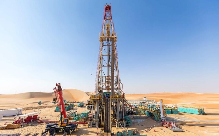
Optimized On-Site Operation Plan for Drilling Mud Treatment System
As global energy demand continues to grow, oil and gas exploration and development activities are becoming increasingly frequent worldwide, which has also brought about corresponding environmental issues. During the drilling process, a large amount of waste drilling mud is generated, and if not properly treated, it can cause serious pollution to the surrounding soil and water bodies. Therefore, how to efficiently and environmentally-friendly treat these wastes has become an important issue that the oil and gas industry urgently needs to solve.
As a professional manufacturer of solids control systems in China, HL Petroleum has developed a complete waste drilling mud treatment system and proposed a corresponding on-site operation plan to address this issue. The plan aims to ensure the stable and efficient operation of the treatment system and minimize the impact on the environment.

System Overview
The waste drilling mud treatment system has a processing capacity of: mud-water separation 8m3/h, wastewater treatment 10m3/h, and overall processing capacity 7.5m3/h. The mud cake after treatment has a moisture content between 35.1% and 45.3%, meeting environmental protection requirements.
According to the different process objectives, the system is divided into three independent units: primary mud-water separation unit, wastewater deep oxidation unit, and separation and purification unit. Each unit is an independent module with a separate control system to ensure the coordination and cooperation of each process step.
To facilitate the installation and maintenance of the equipment, the entire treatment system should be as close to the mud pit as possible. According to the specific dimensions of the equipment and construction requirements, the site area required for the system is approximately 11m × 20m.
Key Equipment Configuration
The main supporting equipment includes filter press, mud pump, pneumatic gate valve, screw conveyor, belt conveyor, brick machine, mixer, air compressor, air receiver, filter tank, water tank, clean water pump, and other auxiliary equipment.
The main supporting equipment of this treatment system includes:
Filter press (1 unit): used for dewatering the mud to obtain mud cakes with relatively low moisture content.
Mud pump (2 units): responsible for transferring the mud to the filter press.
Pneumatic gate valve (3 sets): used to control the flow direction of mud and water.
Screw conveyor without shaft (2 units, 10m; 1 unit, 5m): to transport the mud cakes after filtration to the brick machine.
500 belt conveyor (1 unit, 6m): to transport the bricks produced by the brick machine to the storage area.
Non-fired brick machine (1 unit): to make bricks from the dewatered mud cakes, realizing resource utilization.
Mud mixer (1 unit): to mix the mud, ensuring the uniformity of the mud properties.
2.6/8 electric air compressor (1 unit): to provide the compressed air required by the system.
2.5m³ air receiver (1 unit): to store the compressed air.
10x2.5x2.4m filter tank (2 sets): for deep treatment of the wastewater.
10x2.5x2.4m water tank (2 sets): to store the treated clean water.
Clean water pump (1 unit, 3kW): to transport the treated clean water to the designated location.
Auxiliary equipment such as operation boxes, control panels, air control pipelines, and electrical cables.
The reasonable configuration of these equipment ensures the efficient operation of the entire treatment system.
Personnel Arrangement
According to the different process flows, the personnel arrangement for this treatment system is as follows:
Unit 1 (mud extraction, testing, filter press unloading, mud cake transportation, etc.) has a relatively high workload, and 3 people need to be arranged for operation. Specifically, 1 operator: responsible for key processes such as mud extraction, testing, and filter press operation. 2 laborers: to assist the operator in completing tasks such as mud cake unloading and transportation.
Units 2 and 3 (wastewater deep oxidation and separation and purification) have a relatively low workload, mainly for water purification treatment, and the amount of dissolved reagents required is also relatively small. Therefore, only 1 management personnel is needed to be responsible for the operation and monitoring of the equipment.
Through reasonable personnel arrangement, the smooth progress of each process step can be ensured, and the waste of human resources can be avoided. At the same time, the professional skills training of the operators is also one of the key factors to ensure the stable operation of the system.
Processing Capacity
The treatment system can process approximately 60-100 m3 per shift, which can basically meet the waste drilling mud treatment needs of a single drilling operation. If there are special circumstances, such as high drilling intensity or poor mud properties, the number of shifts can be appropriately increased or the equipment operating parameters can be adjusted to ensure the treatment effect.
In summary, the on-site operation plan for the waste drilling mud treatment system proposed by HL Petroleum has fully considered factors such as equipment configuration, process flow, and personnel arrangement, ensuring the efficient and stable operation of the entire system and minimizing the impact on the environment. As a professional
solids control system manufacturer, HL Petroleum will continue to strive to provide the oil and gas industry with more environmentally-friendly and efficient solutions.

