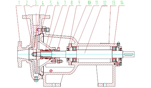
HL spray pump structure and installation method
The oilfield
spray pump is a supporting pump for the mud pump. It is mainly used at oil drilling sites or as a supporting equipment for solid control equipment. The main function of the spray pump is to flush and cool the parts of the equipment during the operation of the main equipment, thereby increasing the service life of the supporting equipment. In some scenarios, the spray pump fluid is also used to transport mud.
The shotcrete pump generally uses a mechanical seal to ensure no leakage during operation. Due to its simple structure and convenient maintenance, it is widely used.
The spray pump consists of a pump body, a mechanical seal pump cover, a mechanical seal, an impeller, and a pump seat. In terms of power, the spray pump is mainly divided into two types: motor direct drive and pulley drive.

1. Pump body 2. Cap nut 3. Washer 4. Impeller 5. Paper gasket 6. Machine seal 7. Pump cover
8. Packing gland 9. Oil seal 10. Bearing cover 11. Bearing 12. Shaft 13. Nameplate 14. Pump seat
When installing the spray pump, first ensure that the installation position should be close to the pumping source to shorten the length of the suction section and reduce energy loss. At the same time, pay attention to keeping the foundation level, firm and reliable to avoid vibration problems.
The service life of the spray pump depends on the calibration standard of the elastic coupling. Under normal circumstances, the error requirements of the pump shaft and the motor shaft are: parallelism offset ≤0.25mm, axis angle error ≤0.12mm. If the inspection result is out of tolerance, the axis should be adjusted to meet the standard requirements by adjusting the installation gasket.
When installing the spray pump, pay attention to the parallelism of the two pulley axes, the tightness is appropriate, and the end face error shall not exceed 2mm; the motor installation must be stable and firm.
When installing the spray pump pipeline, it should be ensured that the cross-sectional area of the suction pipeline must be greater than or equal to the cross-sectional area of the pump flow channel, and a throttle valve is not allowed to be installed in the suction pipeline, but a normally open valve can be installed to reduce liquid flow turbulence. The valve can only be closed when the pump is disassembled for maintenance.
To avoid bubbles in the suction pipeline, the pumping source and the pump should gradually transition from high to low. If the user needs the pump to be used under suction conditions, please use a vacuum pump or a bottom valve to divert water.
The pipeline at the inlet of the spray pump must be straight, and its length must be at least twice the diameter of the suction pipeline. When a hose is temporarily used as a suction pipeline, it must be ensured that the hose is not compressed. This is because the pressure in the suction section is generally lower than the atmospheric pressure. Under the action of atmospheric pressure, the hose is compressed, resulting in a decrease in flow or even interruption of flow.
Finally, to facilitate the maintenance of the spray pump, a normally open valve should be installed in the outlet pipeline. All pipelines (including the inlet pipeline) must have their own support, and the pump is never allowed to bear the weight of the pipeline. When the working conditions are unclear or unstable, a throttle valve must be installed in the outlet pipeline to ensure that the pump operates at the design point.
If you need solid control equipment,
centrifugal pump, Mud Agitator, slurry mixer,
Shale Shaker and accessories, we are the source manufacturer in China and can provide you with satisfactory products. Please contact us.

