WhatsApp: 86-13735815206 / 86-17392256505
WeChat: 86-13735815206 / 86-17392256505
Phone: 86-29-88680837
Mail: sales@hlsolidscontrol.com
Add: Room 804, Building 1, Western Cloud Valley Phase II, Fengxi New Town, Xixian New District, Shaanxi Province
WeChat: 86-13735815206 / 86-17392256505
Phone: 86-29-88680837
Mail: sales@hlsolidscontrol.com
Add: Room 804, Building 1, Western Cloud Valley Phase II, Fengxi New Town, Xixian New District, Shaanxi Province
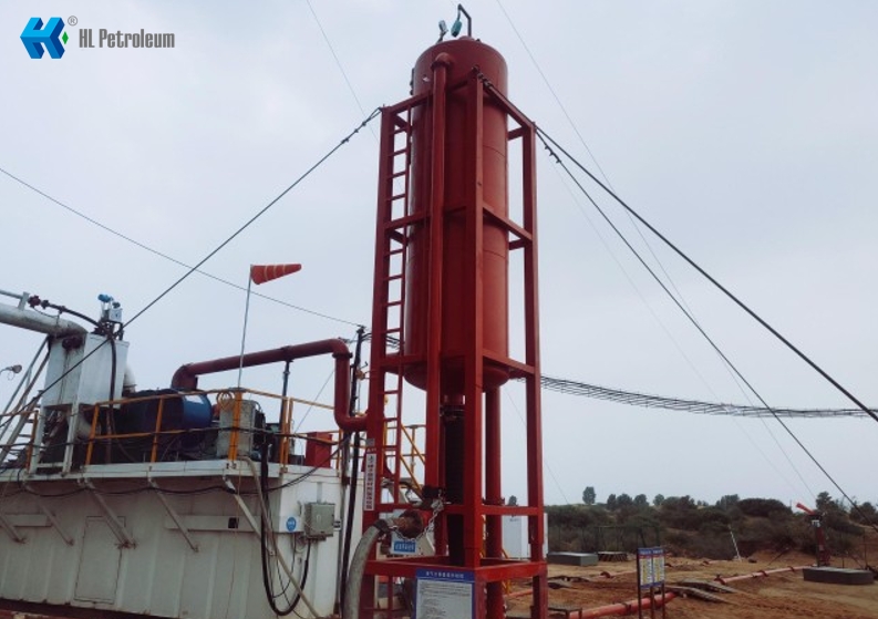
Installation requirements for Mud Gas Separator
Time: 2024-05-21 Source: Solids Control Equipment Author: Mrek
Before installation, confirm that the main parameters of the drilling fluid Mud Gas Separator meet the standard of "Drilling Fluid Liquid-Gas Separator" (Q/SY 1506-2012) and that the processing capacity meets the requirements of drilling construction.
The diameter of the liquid-gas separation inlet pipeline shall not be less than 78 mm and shall be connected by flanges. The diameter of the discharge pipeline shall not be less than 203 mm and shall be connected by flanges. The diameter of the liquid-gas separation exhaust pipeline shall not be less than 150 mm and shall be connected by flanges. It shall be equipped with a backfire prevention device, a combustion torch and an ignition device.
Install the safety valve according to the requirements of the equipment manual. Prepare the manual, product certificate, manufacturer's inspection and pressure test and other technical information corresponding to the equipment.
Liquid-gas separation installation requirements
1. Separator tank
(1) Install after the throttling manifold J8 or J10 near the circulation system. The foundation of the installation location should be flat and solid.
(2) After installation, use a steel wire rope with a diameter of not less than 16mm to fix and tighten it at the three or four corners. The length, width and depth of the cement base pier used for fixing shall not be less than 0.8m×0.8m×1.0m, and the cement base pier shall not be higher than 10mm above the ground.
2. Liquid inlet pipeline
(1) Flange connection and steel ring sealing shall be used, the pressure level shall not be less than 14MPa, and a special elbow of not less than 90° shall be used at the turning point, and throttling shall not be formed. High-pressure fire-resistant hoses of the same pressure level can be used for the liquid inlet pipeline. High-pressure fire-resistant hoses shall be products of manufacturers approved by China National Petroleum Corporation.
(2) High-pressure fire-resistant hoses shall be firmly fixed with cement base piers every 2~3 meters, and safety chains or steel wire ropes shall be used at both ends of the hose for protection.
3. Liquid discharge pipeline
(1) Steel pipelines shall be used, and U-shaped pipe flange connections shall be used. The outlet shall be connected to the drilling fluid distribution tank, and the outlet shall be kept above the liquid level of the drilling fluid distribution tank.
(2) A drain valve should be installed at the bottom of the suspended U-shaped pipe to facilitate drainage.
(3) The outlet of the drainage pipeline should be fixed. When the horizontal suspension length exceeds 6m, the pipeline should be supported in the middle and fixed with a pressure plate.
(4) After installation, the liquid level in the tank should be between 1.3 and 1.6 m.
4. Exhaust pipeline
(1) Steel pipelines should be used with flange connections.
(2) The outlet should be no less than 50m from the wellhead, no less than 75m for sulfur-containing oil and gas wells, no less than 1.5m from the blowdown pipeline, and no less than 20m from the outlet to various facilities other than the blowdown pipeline.
(3) Install pressure measuring flanges, stop valves and pressure gauges at a place convenient for observation on the ground. The stop valve pressure rating is 4MPa, the pressure gauge measurement range is 0~0.16MPa, and the dial diameter is 100mm.
(4) A short-circuit with a drain valve should be installed in low-lying areas.
(5) Anti-backfire device and ignition tube are installed at the outlet.
(6) The turning angle is not less than 90°. The turning point and ignition device should be fixed with cement base piers. The length × width × depth of the cement base pier is not less than 0.5m × 0.5m × 0.8m. The ignition device is fixed with at least three steel wire ropes with a diameter of not less than 12mm.
(7) A safe, fast and effective ignition device is configured. The ignition device has a remote ignition function.
5. The diameter of the sewage pipeline is not less than 100mm. It is controlled by a butterfly valve and the outlet is led to the sewage pool.
6. The pressure level of the safety valve matches the pressure level of the separator and is installed at the top of the tank. The outlet direction of the safety valve should be consistent with the outlet direction of the main blowdown pipe line. The outlet of the safety valve should not be connected to the pipeline.
7. The Mud Gas Separator should be equipped with a pressure gauge. The range should be selected according to the principle of adding 1/3 to the rated value of the separator pressure level. The dial diameter is 150mm. The installation direction of the dial should be consistent with the front of the derrick and installed vertically, and a stop valve should be installed in front of the pressure gauge.