WeChat: 86-13735815206 / 86-17392256505
Phone: 86-29-88680837
Mail: sales@hlsolidscontrol.com
Add: Room 804, Building 1, Western Cloud Valley Phase II, Fengxi New Town, Xixian New District, Shaanxi Province
Oilfield mud level alarm
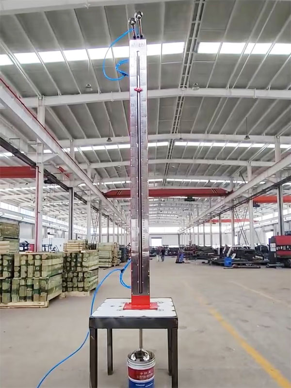
An oilfield mud level alarm is used for mud level alarm, belonging to the manufacturing technology field of drilling mud level alarm device. The new mud level alarm changes the existing technology of inaccurate liquid level measurement by soft rope connected float, and the problem of using sound waves or light and other electronic products to test the liquid surface, which is easy to be damaged in harsh environment. The new mud level alarm adopts the principle of mechanical transmission and pneumatic sound alarm, and designs a drilling mud level alarm with hard connection between float, test and alarm equipment. As long as the pre-setting is correct, the measurement will be accurate. Since there are no electronic components, it can adapt to relatively harsh working environment during use, and it is easy to reset.
An oilfield mud level alarm includes a level control and alarm device, characterized in that the device includes three parts: level indication, limit transmission and alarm control:
The level indication part includes a float, a float upright, an upright slide, an alarm base, a guide plate and a scale. The lower end of the float upright is connected to the float, and the upper end is connected to the guide plate. The guide plates are respectively sleeved on the scale, the vertical pipe and the row rod, and fixed to the top of the float upright. The upright slide is fixed on the alarm base, and the alarm base is connected to the tank surface of the mud tank.
The limit transmission part includes a riser, a straightening plate, a valve box, a travel rod, upper and lower limit cards, a lock tongue, and upper and lower return springs. One end of the straightening plate is fixed to the lower part of the riser, and the other end is fixed to the lower part of the travel rod. The upper and lower limit cards are fixedly arranged at the upper and lower ends of the guide plate on the travel rod. The upper part of the travel rod passes through the lower straightening sleeve and the upper straightening sleeve arranged on the upper and lower end surfaces of the valve box. A lock tongue with a shift fork is fixedly arranged on the travel rod between the upper straightening sleeve and the lower straightening sleeve, and a return spring is arranged at the upper and lower ends of the lock tongue.
The alarm control part includes an air source pipeline, upper and lower air valves and an air horn. The air horn is arranged on the top of the valve box. The valve stems of the upper and lower air valves are in contact with the upper and lower surfaces of the shift fork respectively. The input ends of the upper and lower air valves are connected to the air source pipeline, and the output ends of the upper and lower air valves are connected to the air horn by pipelines.


